
Its very easy to make if you dont get mess with this description
Description:
The early version of this little helicopter was first published in 1996 as a free plan i. It has been built successfully by many people, so here’s my update to celebrate it . All credit for inspiration must go to USA’s John Burkham and Alpha who gave us all the know-how with his Penni helicopter design so many years ago! My variations on the theme were designed to make better use of the then new FAI Tan rubber, which had a capacity for many more turns but at considerably less torque than the Pirelli everyone used at the time.

The Helicopter has a lower pitch, higher revving rotor in a configuration which allows for a bit more forward air speed. It has proved very durable in service. Construction is not too tricky, but will require some of your best inspired “eyeball engineering”, plus careful weight watching! Apart from the normal aircraft modeller’s hand tools, a variable speed mini motor tool is essential, together with some abrasive cutting discs and their mounting mandrel . I prefer to use a jeweller’s “Archimedes” spiral drive hand drill for small bearing work, as you can control the drilling speed, and they don’t tend to gallop away off centre like faster electrics. One absolute must is good EYE PROTECTION!!!! Cutting discs and small turned objects have a habit of disintegrating with zero warning if over stressed, so please remember that you only get the one pair of eyes!! --- end of lecture.
A preliminary note about the free plan: When the plan is printed at A4 size printer programs will sometimes default to around 94% on the paper. To get around this, go into printer preferences and select layout; next select enlarge/reduce custom, and re-set it to 100% It will fly perfectly well at the 94% size by the way!
Main rotor:
The simplified main rotor is the heart of the updated design, and it requires a carved “pitch block” to form the blades.If that idea puts you in a state of panic, don’t worry - it’s about the easiest carving job ever!
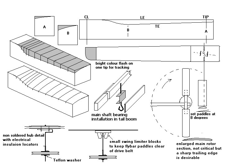
As indicated on the Plan below, the basic block is a one inch square length of straight-grained medium balsa wood (light wooden chop sticks) . The entire leading station is at block top height, and the trailing edge contour is drawn on the opposite side. My technique is to join the LE and TE lines with (non critical) razor-saw cuts at small intervals, and then to knife out the little unwanted wood triangles to reveal the basic shape. Leave the knife cuts a little proud of the surface to allow for slight rounding of the face to form the blade’s essential undercamber - a narrow (1/2”wide) concave sanding block seems a good tool for this final shaping. Try to keep the sharper hub end curves smooth and flowing.
Cut the main rotor from the balsa wooden block in this shape below

Blade production:
Microwave ovens are terrific for heat forming wet balsa, and they have long been my choice for quick rotor/prop cooking! Soak two slightly oversize 1/32” balsa blade blanks in water for ten minutes, then blot off as much surface moisture as possible before applying a sparing layer of PVA white glue on one surface and pressing together. The method is to cover the former block in food-wrap, and then bind the prepared 1/32” balsa laminate to it with 3/16 rubber strip, leaving air gaps between the turns: use no more rubber tension than the job needs, as it can leave marks on the wood if over tight. You will also need to incorporate a little balsa block (plus wrap) under the binding, but above the centre section to keep the hub area dead flat. A food wrap marked “microwave safe” sounds the best option to use.
To bake the laminate, place a coffee mug two thirds filled with cold water in the microwave alongside the former with its laminate, then operate at full power until the water boils (about 2-3 mins). Change the hot water for cold and do it once more . When the binding is removed (like unwrapping an Egyptian mummy!) the result should be a rigidly set and completely dried basic blade form. Magic! By the way, never omit the mug of water or the oven can damage itself! All vessels must of course be microwave safe, and remember not to use any metal items (pins etc). If you really don’t like the sound of all this cookery, just omit the microwave stage and put the laminate on a radiator to dry - it will take a very long time to cure properly however. Whatever method you choose there may be some very slight span-wise bowing of the finished laminate: a little local steaming and gentle bending soon remedies this. Trim your blades to final outline, mark the centre lines, and join accurately at the hub with two 1/32” balsa plates. When all is dry, sand in the simple aerofoil smoothing into the lifting areas. I’ve drawn two hub hinge assemblies, the soldered tube variety and one for non-solderers. A bit of slop in this bearing is no problem as long as it’s equal both ways! The wire fly-bar rod is sewn and glued to the flat upper surface and has a Z bend to stop it twisting. “Hiller” paddles should be set at a positive angle of 8 degrees and are best made from spruce or bass wood: slot their undersides with a “junior” hack saw to receive the fly-bar.
Rotor mechanism details:
Turn the main rotor pulley from med-soft 1/8” balsa, preferably “quarter grain” (also called C-grain). I mount the blank on the cutting disc mandrel between 1/32” ply washers, then turn it true at low drill speed starting with coarse abrasive paper. The narrow V groove must be sharp at the bottom for belt grip, and a narrow angled scalpel blade used flat like a chisel seems to work as well as anything. Plenty of practise needed for this job, as I seldom get more than one good pulley in three attempts! The tail rotor is pre-mounted with cyano to its shaft and then turned in the chuck.Mount the main pulley on a short length of dummy shaft with its triangular ply bearing plates lightly PVA glued to either side: when the glue begins to grab, spin the shaft between your fingers and adjust the running accuracy by eye -- -- elastic belts are tolerant of slight wobbles.
The pulley drive spring is no fun to make! This comprises several turns of thin (0.020”) brass or steel wire wound on a dummy shaft in the direction of a screw thread; this can be soldered to the shaft during final assembly. An alternative to this process is to wind a steel wire spring on the next smallest available wire size (0.025”) to the rotor shaft, then loosen it until the shaft can be twisted into it; if the turn direction is the same as in the photo it will grip the shaft securely in the driven rotation direction. This is not an easy job, but it does avoid soldering, and also allows painless shaft replacement.
The complete main shaft bearing and bearing assembly can be slid into place from one side if the split tail boom is held in place with just one of its side cheeks. I prefer to use a drilled channel section bearing of thin hard aluminum shaped to fit snugly over the boom. Adding the other side cheek then unifies and completes the structure. Any alternative light, minimum-play bearing you are comfortable with is fine, including a Peck Polymer 1/32” nylon nose bush, but be aware that excess soldering heat can run down the shaft and ruin these! The shaft should be vertical, though a small tilt to the (pilot’s) right is acceptable. All wire and tube used is from “K&S metal centres”, found in good model shops worldwide.

Fuselage and tail rotor assembly:
Not really much to say about the 1/8” thick fuselage structure, except that the only really firm stock required is the motor stick and canopy laminations. All other wood should be medium to med/soft with straight grain: if you use nothing heavy for the tail boom/rotor assembly you can usually get away with virtually no nose ballast on the finished model. The canopy outline does not have to look like a “T Rex!” Choose your personal favourite.


Tail rotor:

Final assembly and adjustments:
The upper rotor mast bends have to be made with the pulley and bearings in place, so take it carefully!! The pictured rotor-head underside shows where the bends are located: the non-soldered arrangement shown is the simplest of the options, and gives you a bit more leeway in adjustments because of the movable “wire insulation” spacers. If you do initially make a total “pig’s ear” of it a simple disc cut will allow withdrawal of the shaft, and another attempt. Shaping the little wire eye to mount the soldered bearing tube is tricky, so practise on a piece of spare wire first! Static balance the main rotor resting on its fly-bar wire before mounting to the shaft, then weight the paddles for accurate lateral balance when assembled.

Rotor tracking:
Clamp your geared rubber winder to the bench, and hold the model’s rotor hook in your other hand: then wind on a hundred or so turns and observe of the spinning rotor disc’s left side edge-on: if the coloured blade tip is flying higher bend the fly-bar following it downwards to correct it, and vice versa. A little adjustment goes a very long way, so don’t rush this task! The elastic drive belt needs the lightest tension you can get away with to avoid power losses, and may benefit from some little Teflon tube and wire guides to keep it on “the straight and narrow.” Belt throwing usually starts on the inbound side of any pulley so keep an analytical eye open for it! I make my belts from “lycra rigging elastic” from
Sam’s models in the UK, but two good alternatives are thin "sewing in” elastic from knitting supply outlets, and thinnest elastic stringing thread (0.5mm) from beadwork suppliers. If possible the thread used should be a textilecovered version for best results. The joining knot must be very small.
Trimming:
Chopstick is very CG (centre of gravity) sensitive, and a balance point slightly ahead of the mast is usually needed. Too far forward a location will produce excessive airspeed and a dangerously fast left turn. I’ve drawn the tail rotor oversize so it can be gradually trimmed in diameter until a slow controlled right circuit is achieved. Good balance is also needed on this little rotor to kill potential wobbles. Some ballast on the right skid will also be required to keep the turn coordinated.
Once the basic trim is set up it never seems to drift off much, and can handle considerable power variations. If the CG is set a little rearward the helicopter will fly in square circuits with little flick turns at the corners - I’ve really no idea why!
A “ballpark” guess for a motor is a loop of 3/16” Tan Supersport rubber. With a slack motor 1.7 times the distance between hooks “Chopstick 2” should be good for 40 seconds at full turns, though super light versions (not mine) have reached nearly 90 seconds!
If you love to experiment, this helicopter offers almost limitless opportunities, including blade/paddle weights and angles, and CG adjustments in both axes.
This model may be scaled down to any size, and the plan geometry will still work fine. My friend Bill Kitching’s 6” span “Matchstick” flies exactly like its big brother, but on a quarter of the motor thickness. Graham Stabler holds the current “smallest” record with a dashing little 3” version, and is now talking about the 1.5” option!
Plan:

Modifications ;
This model is unbelievably cool.
It's moderately easy to build and I made only a few changes from the plan. For turning the pulleys I went with a different method that what the author used. I used a very small piece of brass tubing with an inner diameter of .8mm (1/32; just enough for the prop shaft). Drill a hole in the blank, insert the tube with 2 cm sticking out on both sides and glue in using slow epoxy (make sure that it is square!). Once hardened, I put the tube into my drill's chuck and turned it then. When complete, I just cut the tubes off and it's ready. The tail rotor is similar except instead of using tubing I glued the blank directly to the shaft that I was going to eventually use.
The rotors are two pieces of .8mm (1/32") balsa laminated together and formed on a balsa block while still wet. The plan did not specify where the rotors are supposed to sit with relation from the leading edge of the blades to the edge of the block so I stuck it in the middle. I wrapped a long length of old rubber around the block and blades to hold it overnight while drying. Don't forget to put some wax paper or plastic between the blades and the block!
For the swivel on the rotors I first bent the prop shaft to the right shape and then mounted a piece of .8mm inner diameter alum tubing. The tube can rotate freely and is held in place with two beads and a little epoxy. Once hardened, I then carefully tacked the tube onto the rotors (oil the shaft first) with CA and then used some more epoxy to hold it down. This allows to the blades to rotate from side to side which is vital for the stability of the aircraft.

Conclusion :
This thing is still flying just *great* even though it's over 13 years old. I think it's gotten more flights than any other FF aircraft I have.
One huge improvement I've made is to replace the wooden skids with carbon rods. Besides being slightly lighter they are virtually immune to breaking under normal conditions.
I am seriously considering making another but with some significant changes to make it much lighter.
I'd like to replace the vertical stand and tail boom with carefully rolled tubes. I have several replacement pulleys handy but I might turn a new one laminated with 0.4mm ply and contest grade balsa and then drilled out for serious lightness. The skids will be carbon tubes instead of rods and will be mounted to the bottom of the vertical in an "X" pattern so I won't need landing struts (again to save weight). At this point it will lose much of its scale apperance but that's ok.
The tail rotor will have adjustable pitch to make it easy to adjust with the blades made from 2mm depron foam.
The main rotor will be laminated exactly as before but with stronger tips (perhaps carbon reinforced) to help keep their shape.
I still find it amazing that this will fly as well indoors as a quality peanut. 30 second flights are no problem and with a higher roof I'd love to see if I could get my upgraded version over 50 seconds. That would be AWESOME.
AND THE RESULT IS ---


*** Enjoy Enjoy Enjoy***
What is this helicopter called & do u hav the plans to mak it
ReplyDeleteuhybu[bininiby]
ReplyDeletethat is good
ReplyDeleteWooowww
ReplyDeleteDez
ReplyDeleteamei
Mantap keren ilmu yg sangat tinggi
ReplyDeleteHow do I know if it flies? . .
ReplyDelete