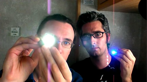
 In this week's Weekend Projects I show you how to make a Joule Thief. The PDF file that goes with the podcast is here(450 kB PDF file). So whats a Joule Thief? It's a little wisp of a circuit that allows you to drive a blue or white LED from a low voltage. Normally, if you want to light up a blue or white LED you need to provide it with 3 - 3.5 V, like from a 3 V lithium coin cell. But a 1.5 V battery like a AA cell simply will not work. But using the Joule Thief, it works like a charm. Not only does it work with a brand new battery, but it works until the battery is nearly dead-- down to 0.3 V. That's well below the point where your other toys will tell you the battery is dead, so it can steal every last joule of energy from the battery (hence the name). To learn how to make one, watch the video, which is available in a variety of formats. |
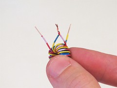
| It's a little hard to see through my fingers in the video, so here's the detailed view of the coil and winding your own. | |
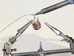
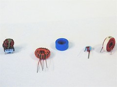 | First, here is a selection of ferrite toroids, inductors, and transformers that are suitable for using to make a Joule Thief. Depending on the type that you start with, you may be able to use the existing wires or need to take them off and wind it yourself. |
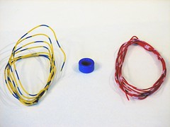 | To wind your own coil, start with two colors of insulated wire and a bare ferrite toroid. |
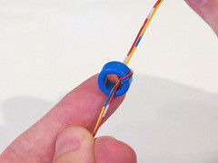
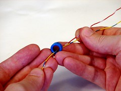 | Take the two strands of wire through the center of the toroid. |
 | Keeping the two strands together, wrap them around and through the toroid again. |
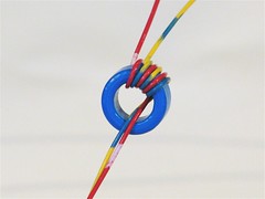 | Keeping the two wires together, make a few more turns through the center. |
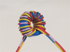 | Keep winding until you fit as many turns as will fit in a single layer around the toroid, typically 7-10 turns with thin insulated wire. |
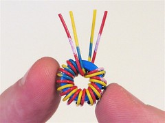 | Clip the wire leads down. Note that we have two pairs of wires: one coming out the front, and one coming out the back. |
 | Strip the wire ends. Take one wire from each pair of different color and attach them together. |
 | Solder the cross-over pair together. This is the "common" point of the coil windings. |
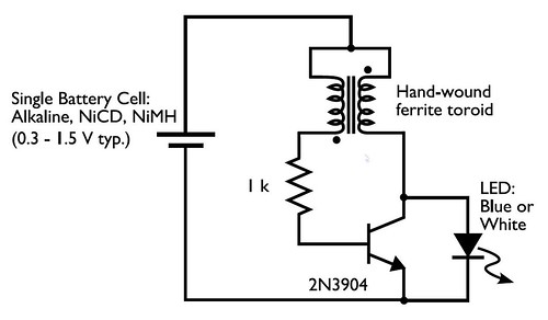 In the circuit diagram for the Joule Thief, the common point of the toroid is the connection at the top of the hand-wound ferrite toroid, in the upper right of the diagram. This goes to the positive end of the battery. The other two wires from the toroid go to the resistor and to the intersection of the transistor with the LED. One other detail that you may need to know is the symbol and pinout of the 2N3904 transistor. In the symbol, the part with the arrow is the "emitter", the "collector" is the end above it, that also connects to the LED, and the "base" is the wire leading off to the left, between the collector and emitter. (Also remember that the end of the LED with the flat side and short lead is the end that has the flat bar in the diagram.) | |
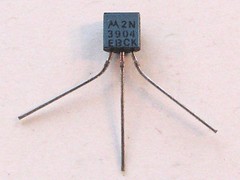 | An actual 2N3904 transistor looks like this. The pins, holding it so that you can read the text on the flat side are (left to right) Emitter, Base, and Collector. I particularly like this one because it has that little EBC legend on the bottom. |
So how does it work? Pretty well, actually. (The technical discussion has been removed.) As a side note, this is not the most efficient circuit around; its beauty is that it works with such a low voltage. So, this is a great circuit to use with a dead or dying battery, and less so for use with a brand new battery. | |
No comments:
Post a Comment